
IPIO User Guide 2.0: Difference between revisions
| Line 143: | Line 143: | ||
<references /> | <references /> | ||
[[Category:IPIO]] | [[Category:IPIO]] | ||
[[Category:Guides]] | |||
Revision as of 13:48, 21 July 2026
Welcome to the new IPIO User Guide
This guide explains how to install, configure, and use the IPIO device using the new web based IPIO Manager 2.0 as part of an Event Gates Safety AI system. IPIO is a network-enabled I/O controller designed to extend control and monitoring capabilities, especially when direct hardware access is needed.
This guide is intended for system installers, technical partners, and end users who need to operate or troubleshoot IPIO modules. It includes detailed instructions on connection, input/output logic, integration with VIS, mute/preset/emergency behaviors, and remote access through IPIO Manager.
How to connect to IPIO with IPIO Manager 2.0
In order to set up and configure the IPIO, you’ll need to connect to it first. While the IPIO Administration API can be accessed in several ways, the easiest and recommended method is using the IPIO Manager software.
- Ensure IPIO is running Plug in the power supply. The device starts automatically. Confirm that the power LED is on.
- Network Connection Connect the device to your local network using an Ethernet cable. The network must not have DHCP enabled — IPIO requires a static IP. If unsure, contact Event Gates support to obtain the default IP address.
- Access web based IPIO Manager 2.0 via a web browser. In order to access the IPIO Manager you need to have it running on a web server. All recent Visbox PCs are deployed with this software installed, therefore just login to Visor with version 2.3012 or newer and click on the IPIO icon the on the menu. Make sure your computer is on the same network and same IP subnet as the IPIO device.
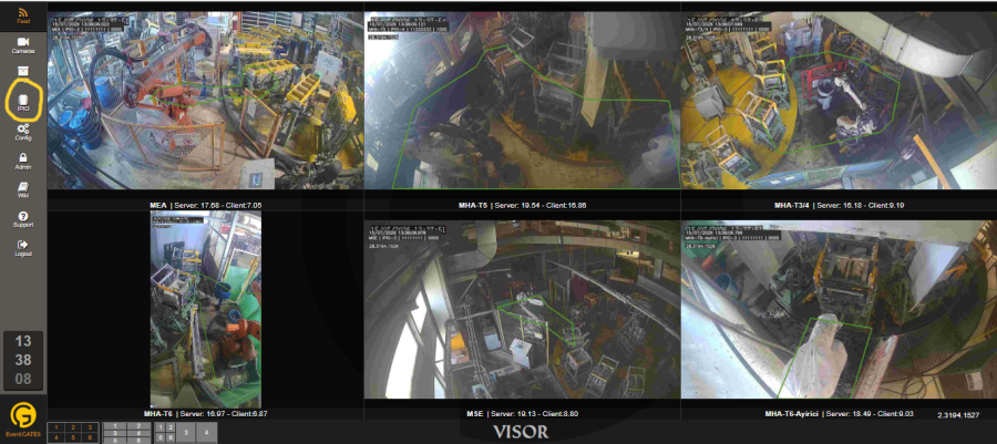
Connecting to the IPIO with IPIO Manager - IPIO link on Visor opens a new tab on your browser and load the IPIO Manager 2.0.

- Connect to the IPIO Enter the IP address, application port, username, and password, then click the Connect Device button. IPIO communicates on port 5000 by default. (Make sure this port is not blocked by your firewall or gateway.)
- Validate connection I/O Control System section will display status of inputs and outputs and System Status on the upper right will turn to Connected.


IPIO Manager may fail to connect for several reasons. See below for troubleshooting.
Using IPIO Manager
You can manipulate IPIO outputs and monitor its current state with IPIO Manager software.
Monitoring and changing outputs
IPIO Manager has 8 buttons to represent its 8 digital outputs. Buttons can switch between red and green representing low and high respectively. You can click a button to set its value. All ON, All OFF and All PULSE buttons under bulk output control section can be used to turn them on or off all at once.
Digital Outputs section also displays the current values of all outputs, eg. if any of the outputs gets manipulated by a third party it's changed value is reflected to the display.
Current input values
Current values on digital inputs are displayed on the respective section.

Administering IPIO
Changing network settings

IPIO communicates over TCP/IP networks. IPIO Manager allows you to change its following network settings:
- IP Address
- Netmask
- Gateway
- Application port: this is the dispatcher TCP port to communicate with and is required to open a connection to the IPIO
Remarks
- Default application port is 5000. Change only if you are instructed by the interpreter developer to do so.
- Save all changes individually. Each save operation requires underlaying IPIO to restart. When saved you will be disconnected and you will need to reconnected with new network settings.
- Follow the monitors for changes and notifications.
How to change username and password

To change username and password follow instructions below:
- Connect to the IPIO you want to update using IPIO Manager software
- Change each credential information (username and password) individually and press save
- Follow monitors for updates and notifications
Important
- Make sure to know your new password. There's no way to recover it once saved.
- Do not change Service Username and Service Password. This is a legacy feature and will be removed in upcoming versions. Service user is not used and attempt to change it's password may break working of the IPIO.
Mute
IPIO is an intermediator between a server and their clients that transforms servers commands to dry contact output and transmits client input to the server. IPIO is specifically designed and developed to work with VIS servers but theoretically it is capable to interact with any server that conforms to its API.
In its standard ODD IPIO reflects a VIS server's commands to some clients, mostly machinery, which can be triggered trough dry contact signal changes. IPIO has a mute functionality which can suppress this servers calls. Mute works with an input signal. The IPIO must be told which input will assume the mute input role in its settings. Mute must be a steady signal and IPIO simple blocks all output commands from the server as long as this mute input is on.
How to set mute input
- Connect IPIO Manager to connect
- Set Mute Input. Options 1-4 for the number of the input channel to be used as mute input, option 0 disables the mute functionality.
Presets
As an integrated IO device for VIS, IPIO offers presets for several modes including mute and emergency. Values for presets are defined under the respective section. Led labeled U2 shows the status of the presets. Under normal conditions U2 is not lit.
For each of 8 output it offers you values from 0 to 3:

0 - Off (low)
1 - On (high)
2 - Pulse (turns on and off automatically)
3 - No change (it leaves the output as it was)
Mute Preset
You may need to set some or all output of the IPIO to a specific position when you mute the system, such as turning red indicator light or a sound alarm on. Mute preset allows you to adjust output of the IPIO to any position you would like it to be set when the system is muted.
Once mute is turned off IPIO starts to obey to VIS commands again but all output set by mute will only changed by a VIS call. (Recovery preset does not apply to mute.)
U2 is highlighted (lit) when muted.
Emergency preset
IPIO may divert to a preferred preset in case connection to VIS is lost. Once a connection is reestablished IPIO returns to normal operation and responds to VIS calls.
How to set emergency preset
Emergency preset accepts options of 0 - 3 for each output individually.
Recovery
When connection to VIS is established IPIO returns to normal operation but any output set to a specific value only changes if VIS sends a specific command for that purpose. In some cases this may not happen immediately or not at all. To handle graceful return to normal operation mod you can set Recovery Preset with same options above for all necessary output.
Working with more than one VIS or IPIO Manager
It is possible for an IPIO to answer more than one VIS. In that case emergency occurs if any given IPIO loses all connection to any VIS and recovers if any VIS is connected no matter if it is the same VIS or not.
It is also important to understand, that any connection established to an IPIO turns emergency mode off. Connections include also those coming from IPIO Manager or any client using the API.
U2 is set to pulse during emergency mode, eg loss of all connections.
Autonomous Pulse
IPIO can be told to autonomously switch an output between states, on and off. To active this setting, output must be set to value 2. Interval of the switch can be configured. It can be set by application and by emergency and mute presets.
Setting pulse interval
To change the time interval between state switches connect to the IPIO with IPIO Manager, change Pulse Interval under Timer Configuration section. Value is in milliseconds. It can be set to 500 and multiples of a thousand. Default is 500 milliseconds.

Logs
This section is still under contruction. Below information may be incorrect.
IPIO has an internal log with a capacity of 2 thousand lines. Log data can be downloaded by selecting the “Download Logs” button. Upon initiation, the GUI may become unresponsive for a few seconds while the system generates the log file.
Upon successful completion, a confirmation dialog will appear (see figure), and a corresponding success message will be displayed on the left monitor. The log file is generated in plain text format, with the filename based on the current date and time.
Updating IPIO Firmware
This section is still under contruction. Below information may be incorrect.
IPIO runs on a embedded firmware which can be updated over a physical or online connection. To update IPIO, press "Update" button, find and select the .bin update file. Update process will started.
After successful completion process of the device will be reset and an information text will pop up. A success message will display.
Caution
Do not update the firmware unless instructed by the Event Gates service team. An interrupted update may harm the device and may require physical attendance.
Troubleshooting connection issues
If you encounter issues when connecting to an IPIO follow the instructions below
Information required to connect
To connect to an IPIO you need following information: it's IP address, application port, username and password.
Make sure you are on the same network and your PC can reach the IPIO by pinging it. If you cannot ping:
- Make sure the IPIO is on and connected to the network with a cable
- Make sure the led lights on IPIO network socket and corresponding switch lights are on and occasionally blinking
- Make sure your PC is connected to the same network
- Make sure you are on the same IP block with the IPIO